
Great Article… Extremely Difficult Tree Removal Solved By Employing Rescue Training Techniques!

Using Caving and Mountaineering Techniques to Transport Wood
By Norm Hall
The client’s home was on a bluff overlooking Lake Michigan. They wanted a better view of the lake. Removing the trees wasn’t a big deal; however, transporting the wood out to the disposal area was a major concern. Photo courtesy of the author
Have you ever had to remove and haul the wood from trees growing on a bluff? We had such a job on Lake Michigan in a North Shore suburb of Chicago. There were approximately 15 of 30 trees to remove, ranging in diameter from 5 inches to 20 inches. Most of the removals were Norway maple (Acer platanoides), with a few black locust (Robinia psuedoacacia) mixed in. Removing the trees wasn’t a big deal; however, transporting the wood out to the disposal area was our major concern.
The only access was a 102-step switchback path going from the client’s bluestone patio to near the bottom of the bluff. Hauling the wood along this staircase would be doable, but exhausting. Was there another option?
Before the bid was given to the client, the sales arborist and I previewed the site to
determine what we thought would be the best method to transport the wood out of the bluff. There were plenty of trees to use as rigging points. We chose to use a highline system. This article will explain our setup process, the advantages and limitations of using this system and how it improved job safety and efficiency.
What led to the job
The home is located in a very affluent neighborhood on a bluff with a beautiful view of Lake Michigan. The bluestone patios on both the first and second floors overlook the lake, but the view to the lake was obscured by the numerous trees on the bluff. The client desired a greater view of Lake Michigan. A neighbor was very satisfied with some bluff work our company had completed on their property, so they referred us to this new client.
This home is in a village that requires all homeowners to obtain a permit for the removal of any tree more than 8 inches in diameter to prevent the removal of “desirable” trees. In addition, a fee is charged based on the species and diameter of the tree(s) being removed. The village forester appraised these trees for removal, and the fees totaled more than $15,000.
The work order
- Remove 15 trees and crown-thin the remaining trees on the bluff;
- Deadwood prune five trees and remove four small, declining trees in the front; and
- Haul all debris.
The job was bid for 10 days. About 85 percent of the work was on the bluff. The majority of the 15 removals were one quarter to three-quarters of the way down the bluff. To help control soil erosion, shrubs, ornamentals and ivy are planted beneath all the bluff trees. To protect the vegetation beneath, we would use rigging lines, blocks and lowering devices.
The lay of the land
This custom-built, multi-million-dollar home is the last one on a winding dead-end street and has a beautiful cobblestone drive. On one side of the home is an 80-foot-long by 4-foot-wide flagstone walkway. The flagstone walkway begins from the drive and ends at a 10-step flagstone staircase heading down to the first-floor patio. Shrubs and ornamentals are planted next to the foundation on one side of the walkway, and an arborvitae hedge screens the neighbor’s home on the other. The clearance along the walkway ranged from 4 to 6 feet. Shrubs and ivy plantings are on the opposite side of the home, leaving no access for debris removal. The flagstone walkway was our only route to haul debris.
This is the anchor tree for the landing. NOTE: This tree was slated for removal, so the lowering line and throw line string were left in the tree (to the left). The lowering line was removed and replaced with throw line string at the end of the day. Photo courtesy of the author.
At the end of the flagstone staircase is a huge first-floor bluestone patio. We needed to walk approximately 40 feet across this bluestone patio to reach a 12-step staircase that leads down to a sitting/viewing area near the top of the bluff. At this point there is a 102-step switchback path, 36 inches wide, that ends at the homeowner’s private beach. The step treads vary from 12 inches to 30 inches.
This is the anchor tree for the landing. NOTE:This tree was slated for removal, so the lowering line and throw line string were left in the tree (to the left). The lowering line was removed and replaced with throw line string at the end of the day. Photo courtesy of the author. »
The pitch of the bluff varies from 40 degrees to 45 degrees. Hauling debris straight up the bluff would not only compromise the safety of our workers, but would also be very exhausting. Using the switchback path was our safest option. Hauling brush and logs from these tree removals was going to be a monumental feat. We needed to explore all of our options.

The bluff slope was about 45 degrees. There was a switchback stairway heading from the deck to the lake, 102 steps total. Most of the removal trees were a quarter to three-quarters of the way down the bluff. Photo courtesy of the author. »
Possible Options
Using a crane.Using a crane was out of the question. The radius from the set-up point on the drive to the first-floor patio was 130 feet. That’s just to the patio, not down the bluff. Renting a crane of that size would probably damage the cobblestone drive, plus be outrageously expensive for the multi-day job.
Using a controlled-speed-line/slide-line technique.We have used these techniques in the past, but the brush would most likely get hung up and/or damage the plants beneath on the way up.
A highline/trackline system.There were plenty of trees to use as rigging points for a highline system, so we explored that. The switchback path had a 7-foot by 12-foot flagstone viewing area approximately three-quarters of the way down that we could use as a brush-stacking area. There was a tall black-locust tree just behind this area that could be used as a rigging point for one of the highline anchors. Near the top of the bluff was a Norway maple slated for removal. We could use this tree as the other anchor, once the trees limbs were removed. Using the above two trees as anchors would keep the brush 30 to 35 feet above grade and the angle of the highline at 10 degrees downward. Since the angle of the highline was pitched down, we needed to incorporate a haul system to get the brush and logs uphill to the Norway maple. This would mean using a rigging plate. We also had to figure out a way to haul the brush and logs up the 30- to 35- foot height of the highline.
The brush staging area at the bottom. Photo courtesy of the author.
Caving and mountaineering rescue techniques.I have been reading caving and mountaineering rescue books for 15 years. Mountain rescuers can build a rope system to hoist an injured climber from rock faces to the top of the cliff for patient transport.
Using both the highline/trackline and mountaineering rescue techniques, we could build such a system to transport wood up the bluff. I have a half-inch by 200-foot static line that I use for “slide lining.” About 20 years ago, I made a steel parallelogram-shaped plate from three-quarter-inch steel. The original purpose was to use it for slide lining. I drilled seven five-eighths-inch holes to accommodate 11mm steel locking carabiners (three on the top, three on the bottom and one on the uphill side). The uphill side hole was used as the control/haul-back line. The steel plate weighs 5 pounds. I keep three half-inch screw-pin shackles on this plate to use as links for the rescue pulleys. I like using screw-pin shackles to eliminate the possibility of a carabiner accidently opening. My thought was to use the steel plate as the transport carriage. All the other hardware and software, which included rescue pulleys, steel pear links and various ropes, were readily available.
The setup was going to be a little complex and there would be extremely high forces on the two anchor trees, which we had to be cognizant of. The setup would be as follows.
The half-inch by 200-foot static line would be anchored between the two trees.
A trolley system consisting of the rigging plate, connecting links and pulleys would be set up on the highline.
Haul-back/pull lines would be anchored to the side of the rigging plate.
A reeving system would be used that was able to go up and down in a controlled manner, using a tending micro pulley attached to the bottom of the rigging plate.
Performing the job
To eliminate any confusion, we sketched a diagram of the system so everyone was on the same page. Now we were ready to set up the highline.
The Norway maple tree near the top of the bluff was limbed up to the highline anchor point. We left the top of the tree to help with dampening the forces. The rigging friction saver, highline and haul system were installed. The black-locust tree near the bottom was without any branch unions where we wanted to anchor the highline and haul system, so it had to be climbed to set the rigging. Otherwise, we could have set this system using a throw-line string.
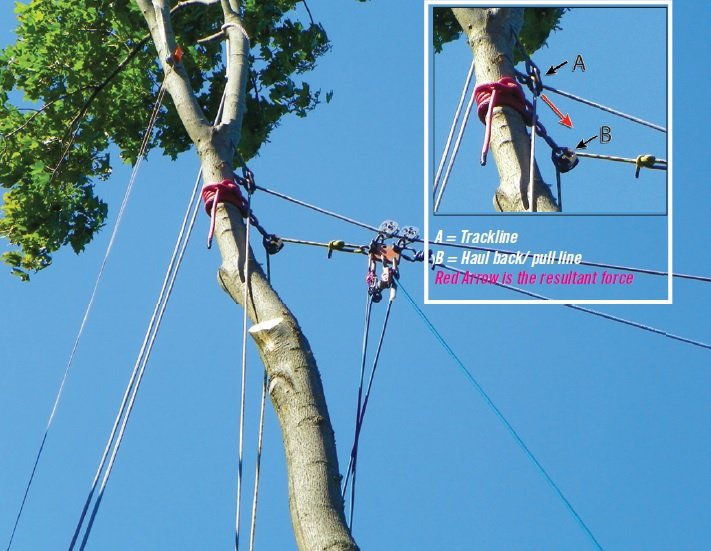
Due to the extremely high forces involved on the two anchor trees, we chose to thread the trackline through rigging friction savers and anchor them to Port-A-Wraps near the base of each tree. This setup served a dual purpose: (1) the resultant forces generated were directed on an angle, instead of horizontally; and, (2) the trackline rope tension was easily adjusted from the ground.
Speaking of the ropes tension, the static rope was not taut. We left a little slack to reduce the vector forces.
NOTE: Had we tensioned the static rope and not left any slack (180 degrees), the force on the anchor points would have been extremely high. Keeping the rope at a 175-degree angle with very little slack can generate vector forces up to 11 times the load. While in the two trees, we also installed the pull/haul-back pulleys, using spliced-eye slings, steel locking carabiners and rescue pulleys.
The next step was to install the rigging plate assembly onto the highline. Using two of the top holes, we anchored two CMI RP104 rescue pulleys to two half-inch screw-pin shackles. Using two pulleys helped spread the weight on the highline and prevented the rigging plate from rotating. The pins on the screw-pin shackles were torqued tight. Using the one side hole, we anchored one of the haul lines to the third screw-pin shackle. Since there wasn’t a hole on the opposite side, we chose to use a 10mm pear link connected to one of the top screw pin shackles, then tied the rope to that. Now we had a trolley system that could be moved back and forth between the two anchor trees.

The heart of the system, “The Carriage,” a piece of 3/4-inch steel

The reeving system was rigged with a 2-to-1 mechanical-advantage system to a “hitch-climber” pulley at the top. A hitch cord tied with a “VT” held the load once hoisted. Photo courtesy of the author.
Our last step was to install the haul system. We utilized all three holes on the bottom of the plate. This system was going to be very similar to an upside-down DdRT (doubled-rope) climbing system utilizing a PulleySaver. Using it in this configuration would give us a 2-to-1 mechanical advantage on the haul/lowering system.
We used a half-inch by 150-foot All Gear Blue Finish Line (static rope) as the haul rope. This rope had a sewn eye on one end, which was anchored to an end hole using a steel locking carabiner. The middle hole had a DMM Hitch climber pulley anchored to it using another steel locking carabiner. The Blue Finish Line was threaded through the Hitch Climber pulley, leaving a bight of rope for a CMI RP104 pulley that would be used for the “haul system.”

An illustration of the slope and trackline setup. Photo courtesy of the author.
A hitch cord was anchored to this rope (using a VT, or Valdotain Tresse knot) to capture and hold the rope once it was loaded. The other end hole had a micro pulley anchored to it using another steel locking carabiner. This micro pulley would hold a quarter-inch rope that would be used to collapse the VT and lower the load.
The CMI RP104-pulley haul system had a steel carabiner on it, which had a 3/8- inch fixed loop connected to it for hauling logs. When we hauled the brush, we switched to an eye-and-eye choker.
With the system installed, we were ready to transport the loads.
We positioned two workers at the brush/log staging area (#1, #2). These workers (#1, #2) put the eye-and-eye choker on the brush, then hoisted it up to the rigging plate. Another worker (#3) was up the hill at the base of the Norway maple. Once the load was hoisted to the rigging plate, this worker (#3) controlled the uphill transport of the load. Once the load was transported uphill, another worker (#4) was stationed near the Norway maple. He (#4) pulled on the quarter-inch rope to collapse the hitch in order to control-lower the load to his co-worker (#3) at the base of the Norway maple. The two workers (#1, #2) at the staging area would stack the brush and choke it to connect it to the RP104 pulley.
To ensure everyone’s safety, we limited the loads to 200 pounds, which was about the maximum one worker was able to continually hoist. Keep in mind, we rigged a 2-to-1 mechanical-advantage system which was on two pulleys with bronze, oiled bushings. This resulted in some efficiency loss due to the bushings. After a couple of complete load/hoist/haul cycles, the crew was elated at how easy and efficient the system was to use. All the wood from every tree removed on the bluff was transported using this trackline system. At the completion of the job, removing the trackline system was much easier than the setup.
Summary/End result
Although we had never used a trackline system before, we were able to save the company money by putting it together using the ropes and hardware from our inventory. The trackline system took a couple of hours to set up, but at the conclusion of the job it proved to be very useful and worthwhile, considering the amount of time and energy that was saved hauling the wood up the 102 steps. This trackline system also proved to be a very safe method to complete the job. The client and our company were very pleased with the end result, and I would highly recommend using this method for any bluff-type work.
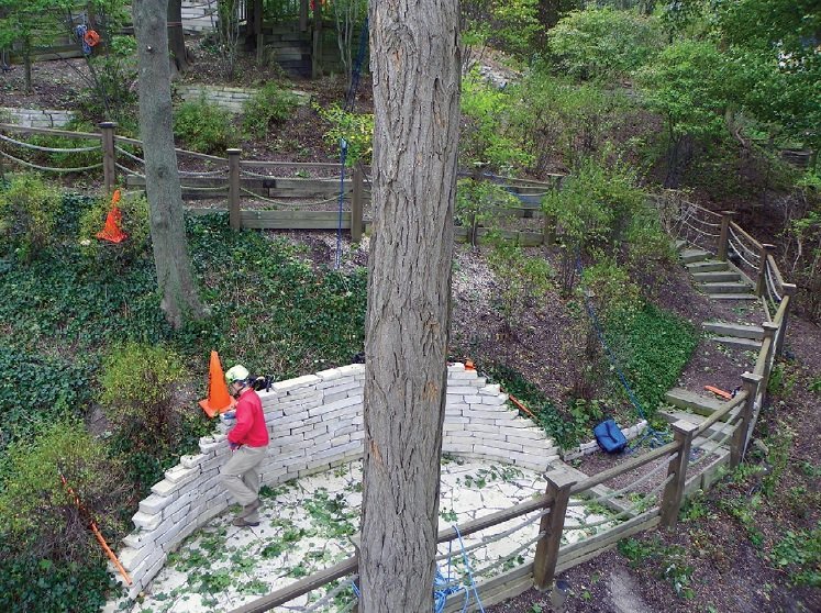
 This the black locust we used for the lower anchor. The trackline is 30-35 feet up. The hoisting pulley is just to the right of the worker. Photo courtesy of the author.
Norm Hall is an ISA Certified Arborist, a Certified Tree Worker Climber Specialist and a lead instructor for the Illinois Arborist Association Advanced Training Program. He has been in the tree care industry for more than 45 years. After several years with Kinnucan Tree Expert & Landscaping Co., an accredited, 41-year TCIA member based in Lake Bluff, Illinois, he recently took a position as a splicer and trainer with All Gear Inc., a 17- year TCIA Associate Member based in Northbrook, Ill.